The 530Cs is a tough machine to love. In IBM's promotional material, along with a lot of it's documentation, the machine seems to share the spotlight with it's slightly smaller and equally tough-to-love little brother, the 230Cs.
Both machines are considered 'ultraportables' with a very small footprint and unfortunately quite unreliable DSTN colour LCD displays.
They also are both notorious for their Varta hibernation batteries along with their main batteries all tend to leak green horrible flaky corrosion.
| Model | IBM Thinkpad 530Cs |
| Machine Types | 2605 |
| Release Timeframe | Sold from May 1995 until May 1996. |
| Preceded by | 510Cs |
| Superceded by | The 535 |
| Motherboard Specs | |
| Display Specs | 8.4" DSTN LCD |
After a long running saga trying to get one of these working, after working through three seperate, non-working machines, I managed to combine the good bits and make one good one. And here it is, working:


At least these machines are easy to tear down and although many have suffered in the humid Japanese climate, they are a fun machine to try and repair. The 230Cs is a successor of the much loved RIOS 'Monolith' PC110 machine, and in some ways this seems to be related.
I have a few of these machines and the journey to have one working complete one is still happening. One of the first things to do is to remove the VARTA battery from underneath the LED status bezel:

Once you've removed a bunch of screws, you can pull the motherboard off from a couple of daughterboards which stay in place. The mainboard has 7 through-hole capacitors which do not tend to leak. If you attempt to replace them, it's worth knowing that i've found the solder to have been originally used on these boards to be quite troublesome. I'm not sure if it requires a higher melting point or it's just really annoying but it's hard to remove and it tends to block your desoldering gun. Use a lot of flux and try and mix in some fresh solder.
On the mainboard which comes off first, here are the 7 capacitors:

On the remaining two daughterboards, there are some surface mounted capacitors:
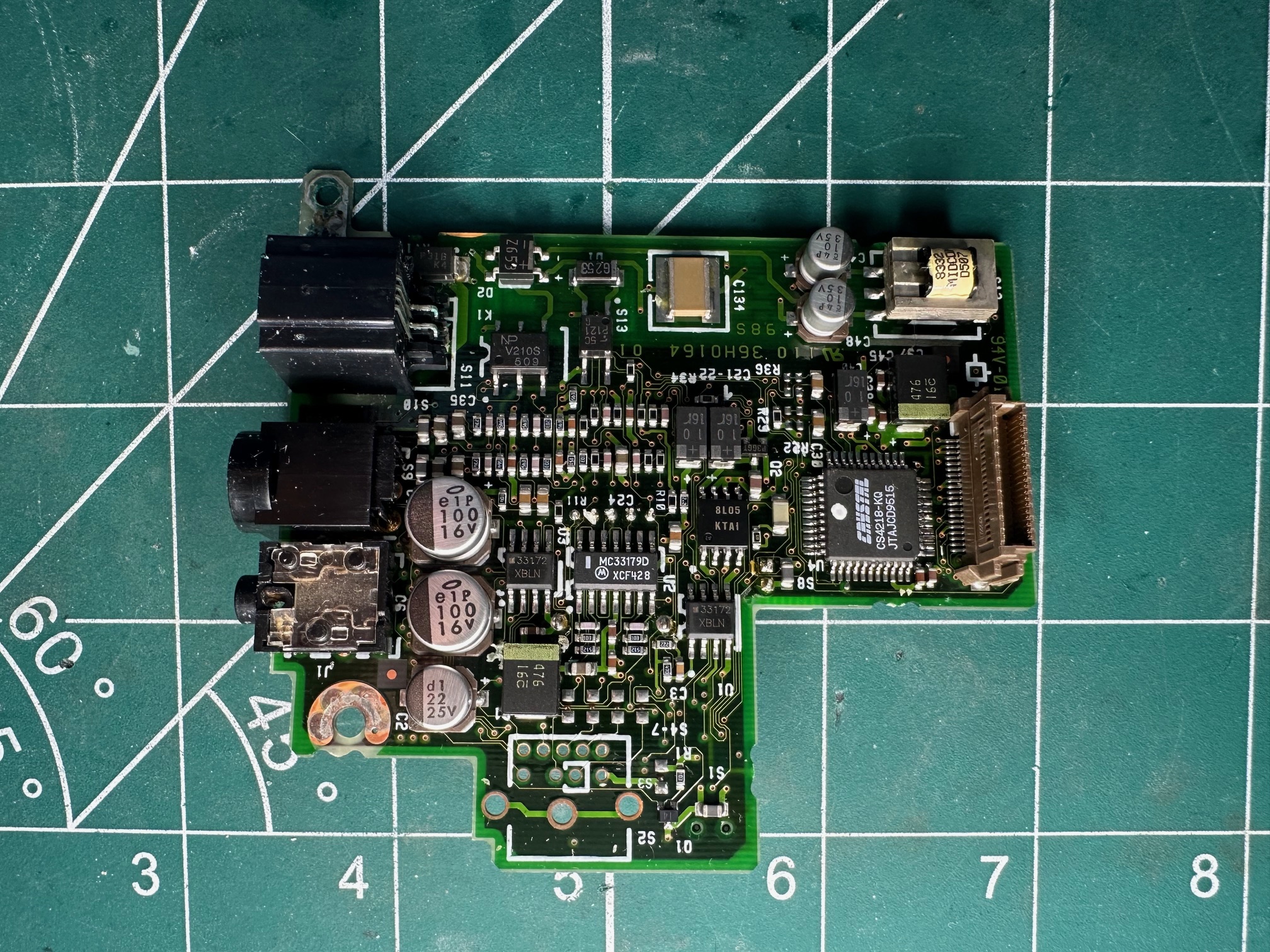
On the daughterboard above, I've tried replacing the small surface mounted aluminium electrolytic capacitors with both new ones, polymer ones and with tantalums and the power delivery seems to work fine using all three - as long as you keep the same number of uF.
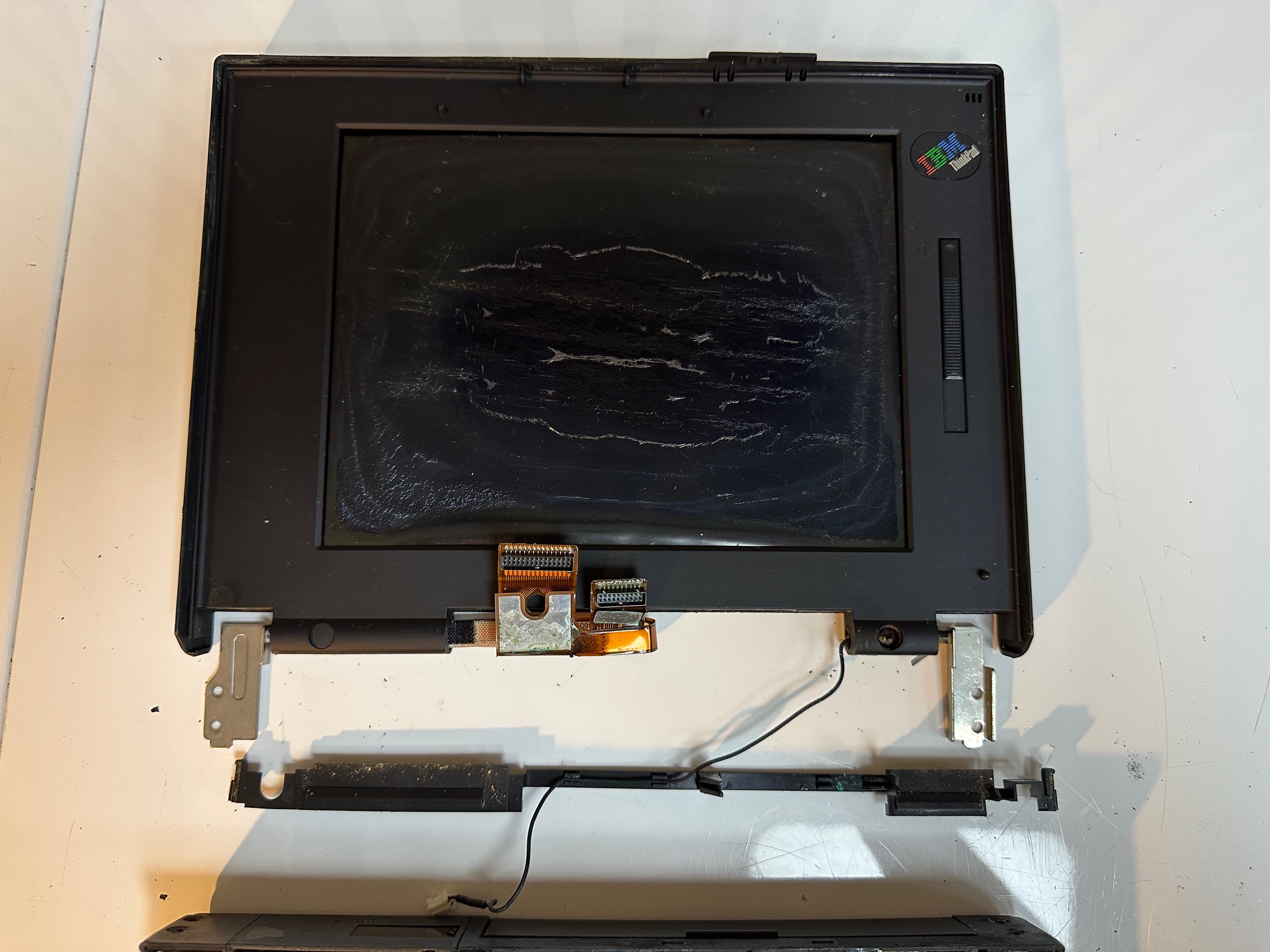
The LCD
The LCD has some very easy-to-get-to capacitors on the back. They were leaking.


Here are some pictures comparing it against the 535X:


Teardown
Here is a complete teardown of the 530Cs. My example here is quite rough with plenty of internal corrosion caused by the Varta hibernation battery. It also has vinegar syndrome on the LCD due to a hard life in Asia.

1) Turn the unit upside down and remove the 4 base screws:

2) Remove the LCD indicator bezel by simply pulling it up (and out of the rear tabs), and then unscrew this centre plate:

3) Snip the IBM branded 3-cell Varta battery out:

4) Remove the 3 screws holding down the top of the keyboard:
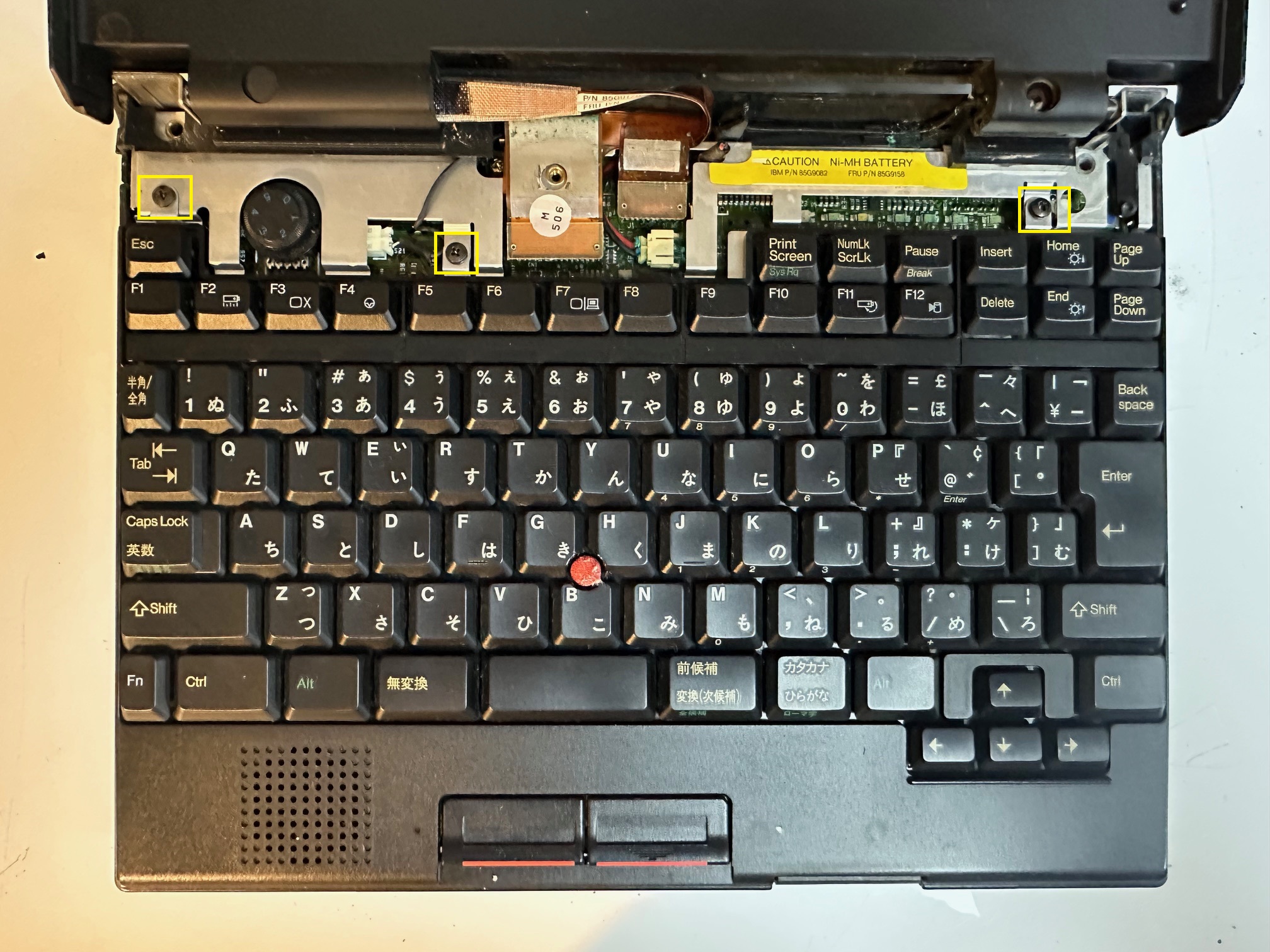
5) Remove the screw under the keyboard inside the floppy connector cover:

6) Unplug the 3 keyboard connectors:

7) Unplug (by pulling up) the 2 screen connectors and the small 2-pin MIC connector:

8) Remove the 4 hinge screws:

9) Slide up and remove the whole lid along with the horizontal plastic standoff that sits underneath it:
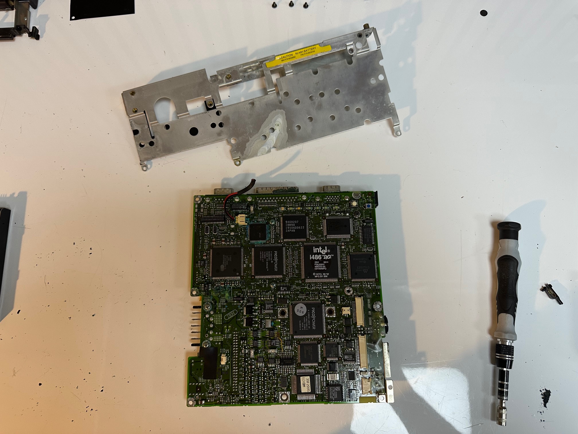
10) Unscrew 6 screws from the motherboard along with the speaker connector:
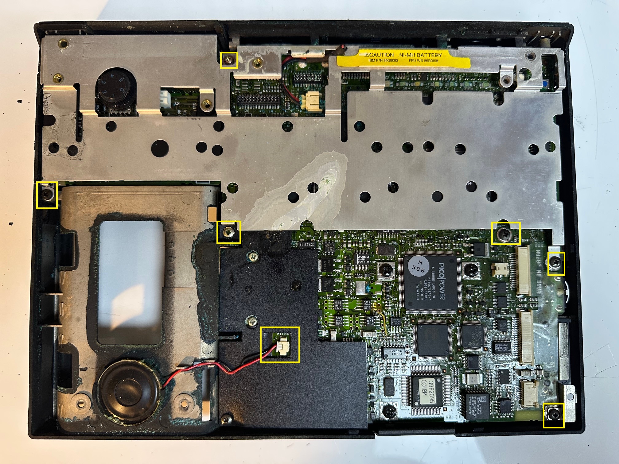

11) Lift off the black plastic insulator:

12) Lift off the motherboard, which is friction-connected to the 2 daughterboards in the middle-left-back section:

13) Remove the top-left screw from the daughterboard:

14) Remove 2 further screws from the daughterboards:

15) Pull out the IR transceiver:

16) Remove the final screw from the daughterboards which holds in the IR cover:

17) With the last of the PCBs removed, here you can see what damage has been done with the leaking green corrosion from the batteries:

18) Back to the motherboard, remove the three HDD screws:

19) If you remove the 6 rear bolts either side of each connector, the metal shielding will also come off (which is necessary to reveal all the fuses):
20) You can also inspect the parasitic damage done by the 3-cell green battery - here you can see that it's seeped through the PCB and damaged a lot of components on both sides. In this case, this motherboard is a write-off:


21) Finally, if this little thing on the left pings out, it's from the top LED bezel and goes in the little reset button:
