The 230cs is the final iteration of the 'monolith' sequence of IBM ultra mobile Thinkpads. There was the original Monolith prototype which was never released, which was succeeded by a production-ready PC110 or PalmTop 110 or PT110 or....TP110. It wasn't allowed to be called a Thinkpad because it wasn't Thinkpad-y enough.

Then there was the Thinkpad 220, which actually wasn't very Thinkpad-y either, because it had a mono screen and a trackball in one corner. Finally, we got a 230cs which is a lovely little machine but it does have two terrible achilles heels:
1) As it originates in Japan only, almost all the screens have succumed to 'Vinegar Syndrome'. I'm midway through trying to get at least 2 of 3 screens working - luckily the Citizen screen in this unit is very easy to disassemble and only has one polarizing layer - the one on top - so less to remove. The LCD also has about 20 tiny through-hole capacitors on the back which do leak and should all be replaced. These citizen screens are one digit off from the PC110 display.
Here is a screen after scrubbing all the hardened snot off:

The scraping of the top layer takes about 90 minutes. The trick is to gradually soak the glue in 100% IPA then do some scraping (everything into the middle) and then repeat.
Here are a couple of pics of the rear:


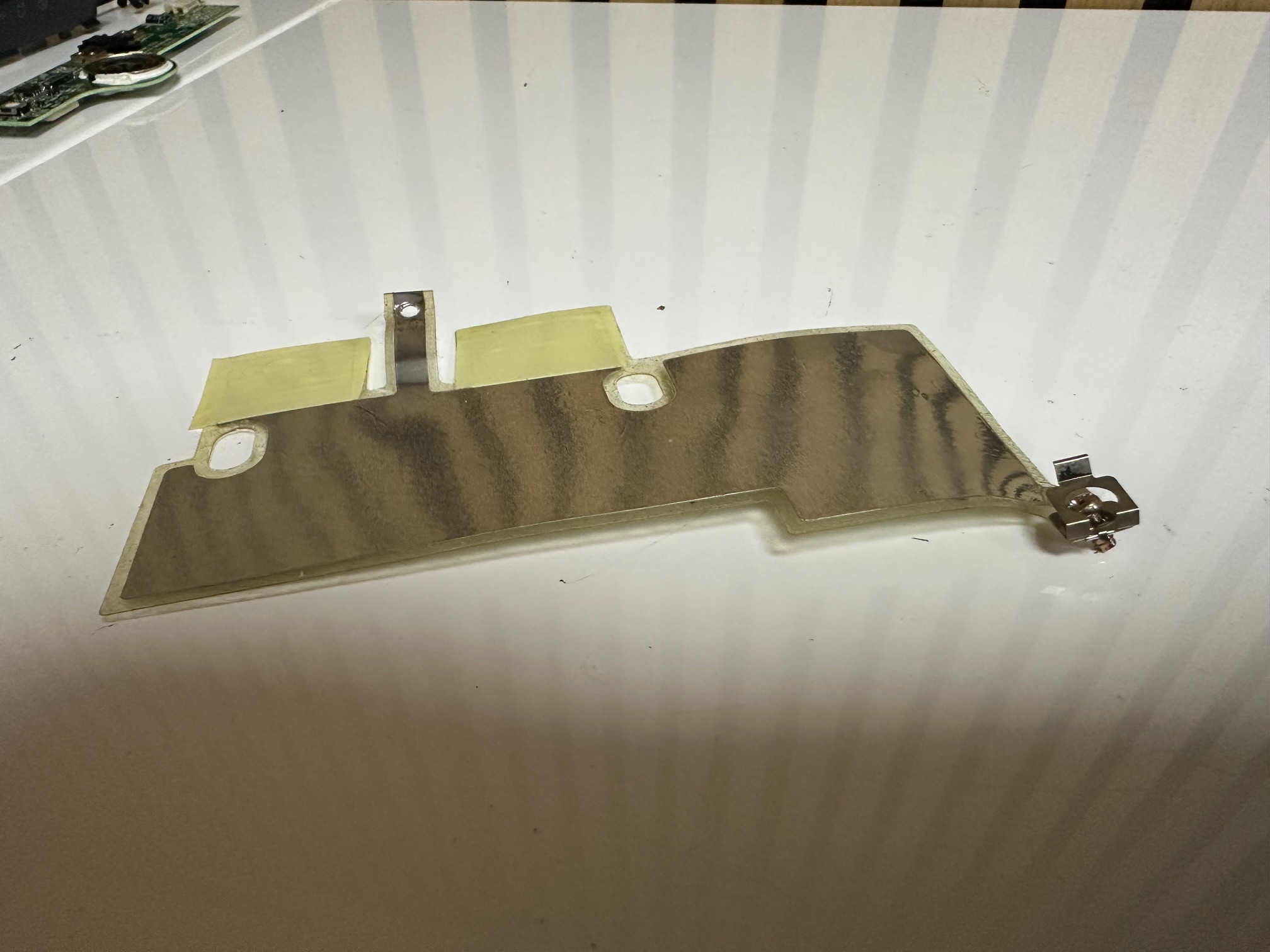
2) The dreaded Varta battery. The battery itself isn't a problem, but there is a board inside which sits next to the power in put and it's refered to as "84G8486 Power Sub-Card with coils and electrolytic capacitors" which is very very affected by the Vatera battery - as it sits directly below it, sandwiching the battery between itself and the mainboard. This tiny DC board has about 7 through-hole electrolytic caps on it and 3 surface mounted ones which don't necessarily leak, but the gases around them have rotted away tracks - the corrosion has begun to eat away at tracks in the PCB and the legs of both the small proprietary connector to the motherboard as well as the legs off the biggest IC on the board have come loose in various places.
This is a rotten board:


This was one of the very few machines' boards which was unaffected by the battery:


Additionally, after seemingly repairing this board, it took me HOURS trying to work out why a so-called repaired board was working sometimes and not other. Under a microscope the legs which hold the board's main connector down were moving all over the place. I managed to reflow one and get it working.

On the left is a machine with a new replacement colour LCD screen. The machine on the right has an original screen with some damage which appears in big circles on the display.


Disassembling the 230cs
1) Remove LCD bezel by prising out the two rubber bungs and removing the screws. Pull off the bezel by spudging the edges.


2) Remove main battery
3) Flip the machine upside down and remove 3 bottom screws - small at the front and longer at the top along with removing the memory bay door and unplugging and removing the CMOS battery.


4) Pop up front of the keyboard by sliding some fingers into the battery bay and pushing up. Keyboard folds over so you can unclip the two keyboard ribbon cables.

5)Pop off the two end hinge covers with your fingernails

6) Unscrew the LCD along with the 2 hinge screws and remove the LCD/inverter from the lid
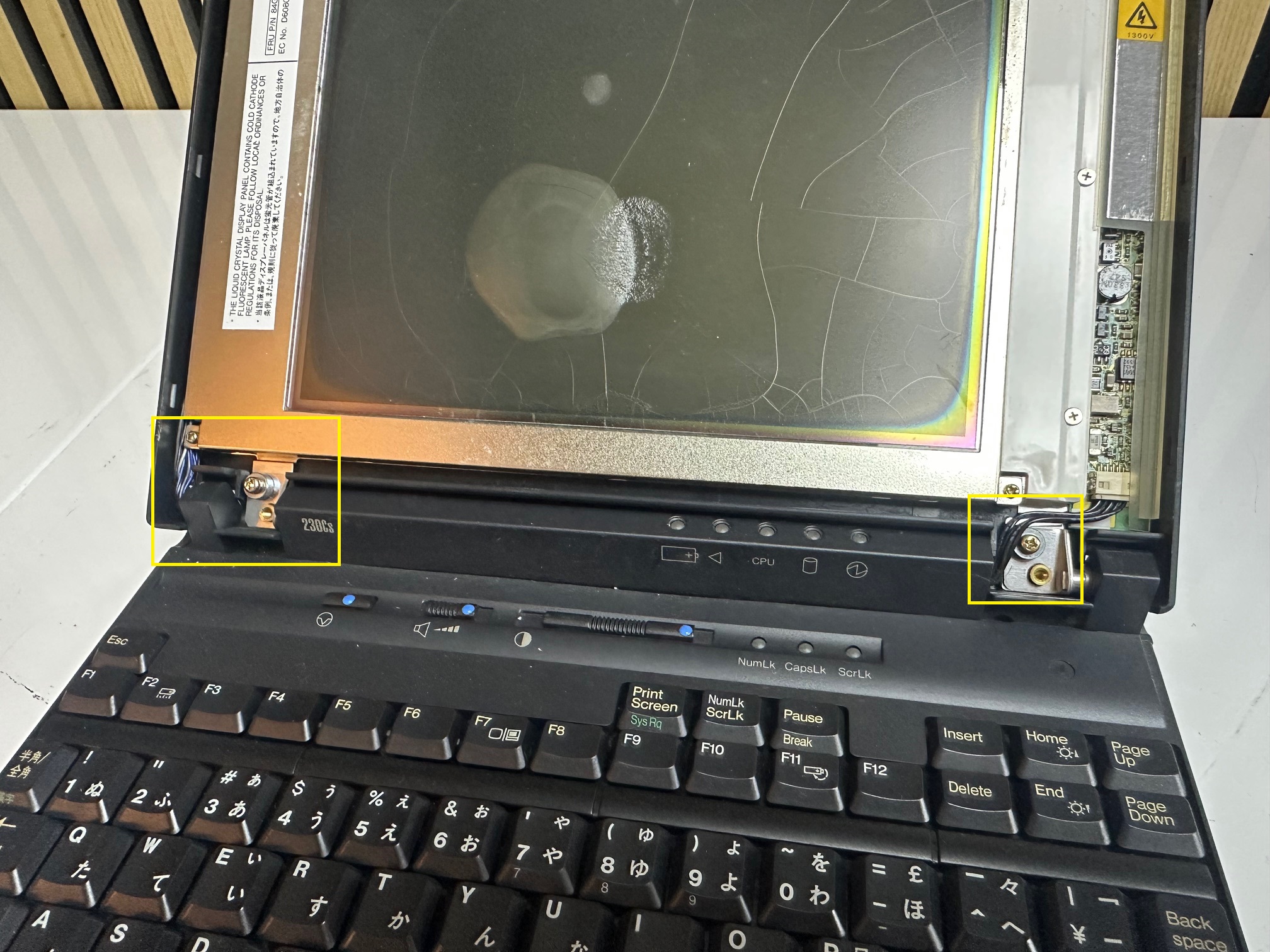
7) There are two black plastic hinge covers in the centre of the hinge - remove the screw in each one

8) Unscrew the 4 bigger golden hinge screws

9) Pop off the LED indicator bezel by pushing out the 4 tabs on the back

10) Remove the hinges and the black plastic hinge covers
11) Unclip the LED indicator ribbon from the speaker board and remove the 3 black screws. The board pops off from the front left.


12) Remove the clipped screws left and right - the right one along with the flexible shield.


13) Remove both screws far back right and left, which attach the motherboard to the base.

14) With your left hand push the PCMCIA eject buttons in whilst lifting the front left side of the motherboard upwards and past the side plastic.

15) Lift the whole innards up and forward, weighing the back section. The whole unit will come out of the base at one item


16) Flipping the board over will reveal the screwed-down 2.5” HDD, the RAM and the DC/DC board on the left. Sandwiched between the DC board and the motherboard is the parasitic battery


17) Lift up the DC board by the connector on the bottom-right and slide it out.
18)Remove the varta and inspect the damage.
More DC/DC Daughterboard notes
Having unwillingly spent another few hours trying to get more success from the DC board, I've had varying degrees of success (or failure, depending how you look at it). One thing I noticed is that sometimes you simply can't replace electrolytics with solid capacitors - they're just not good enough for the sensitivities which electrolytics provide and I've found that in the case of the three 22u / 10v side, surface-mounted capacitors around C46, C47, these simply have to be electrolytics. I've found if you use ceramic or tantalum replacements, the display doesn't tend to power up.
I've also found that the DC/DC board is obviously driving lots of different subsystems and whilst you may feel you've preserved it in such a way where the machine powers on, you find that something else still doesn't work - it could be the internal display or both internal and external.