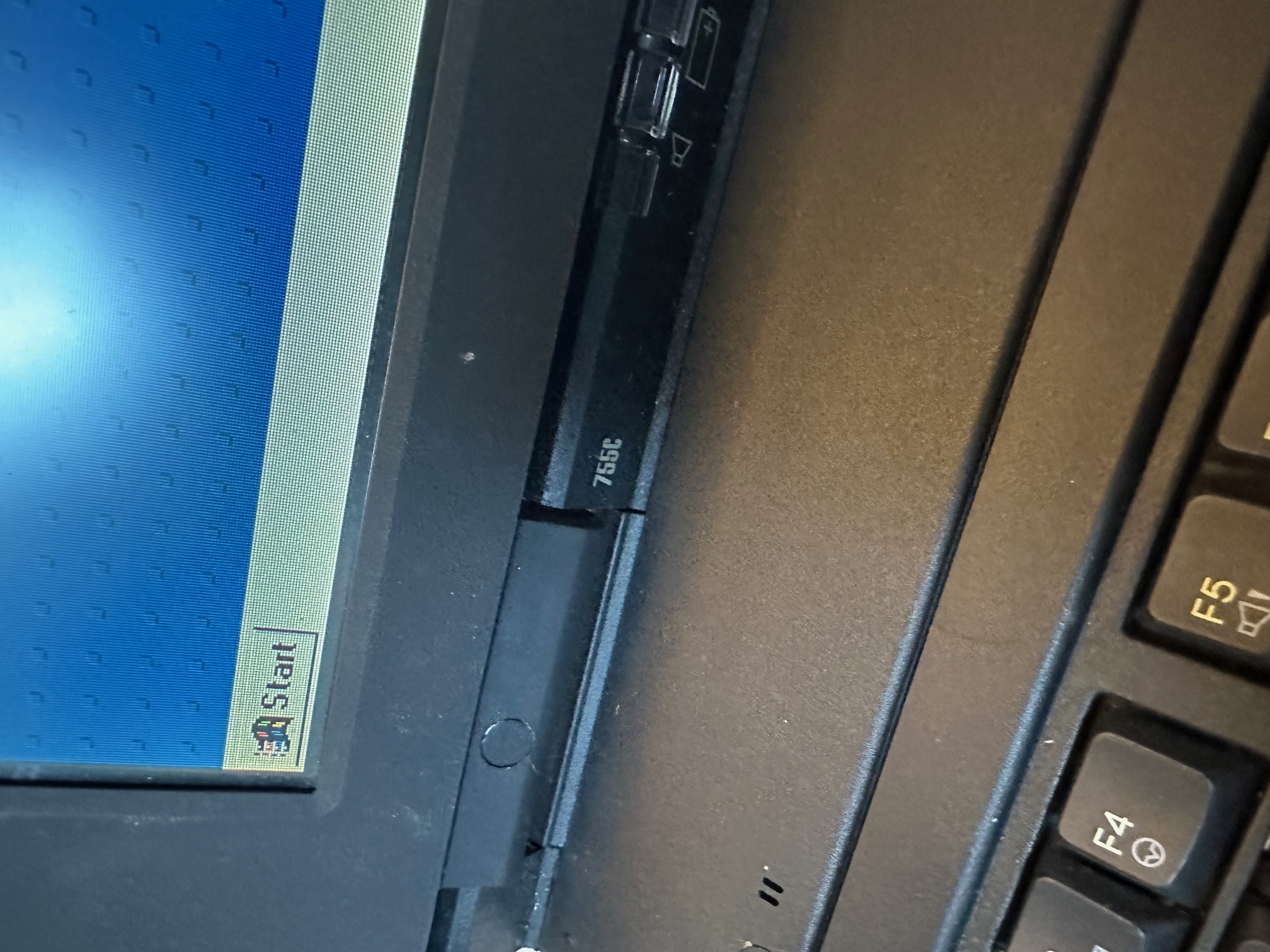
I acquired a foreign (to the UK) IBM Thinkpad 755c. Here are some notes I made considering I spent a few hours today.
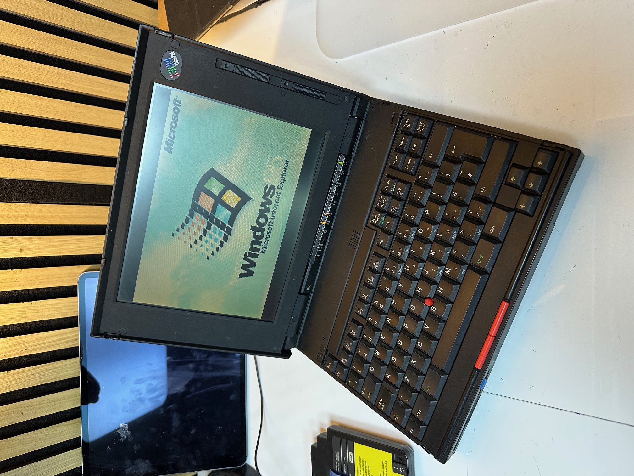
The machine was in good working order, once the battery was removed. With the main battery fitted, the status LEDs just flashed you when you pushed the power switch and all went out. This is a common issue with drained Ni-Mh batteries.
Also the CMOS battery was dead, so I used the old one's wiring to swap in a new 2032, to save having to set the time every single cold boot.
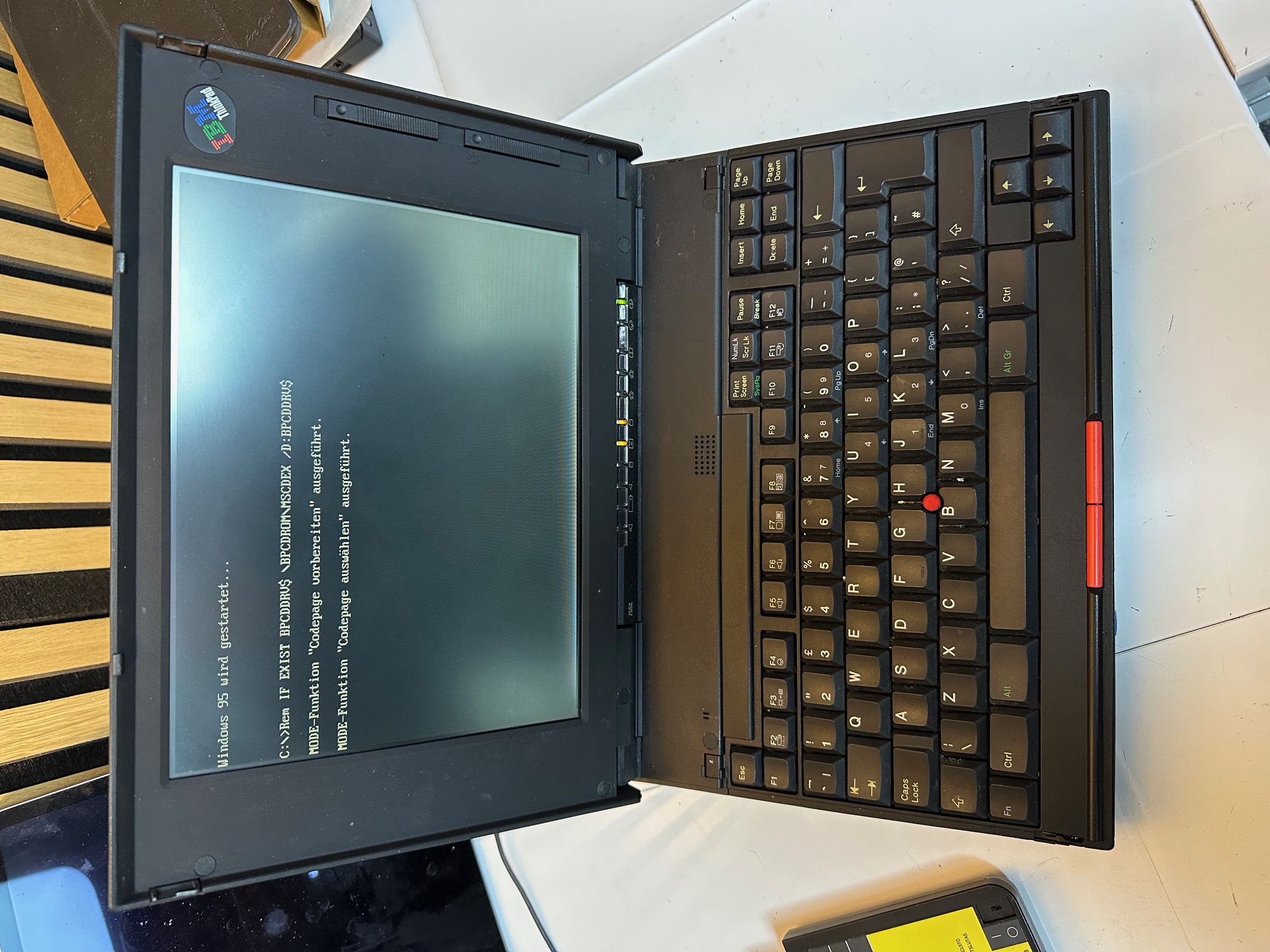
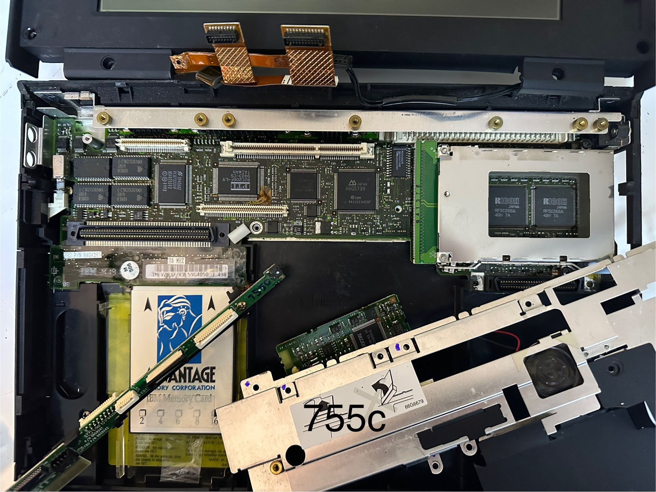
It had the base/built-in RAM only, which was 4Mb, so I found an older, parity IC-DRAM card to go in, which was 16Mb, giving a total of 20Mb. Much faster W95.
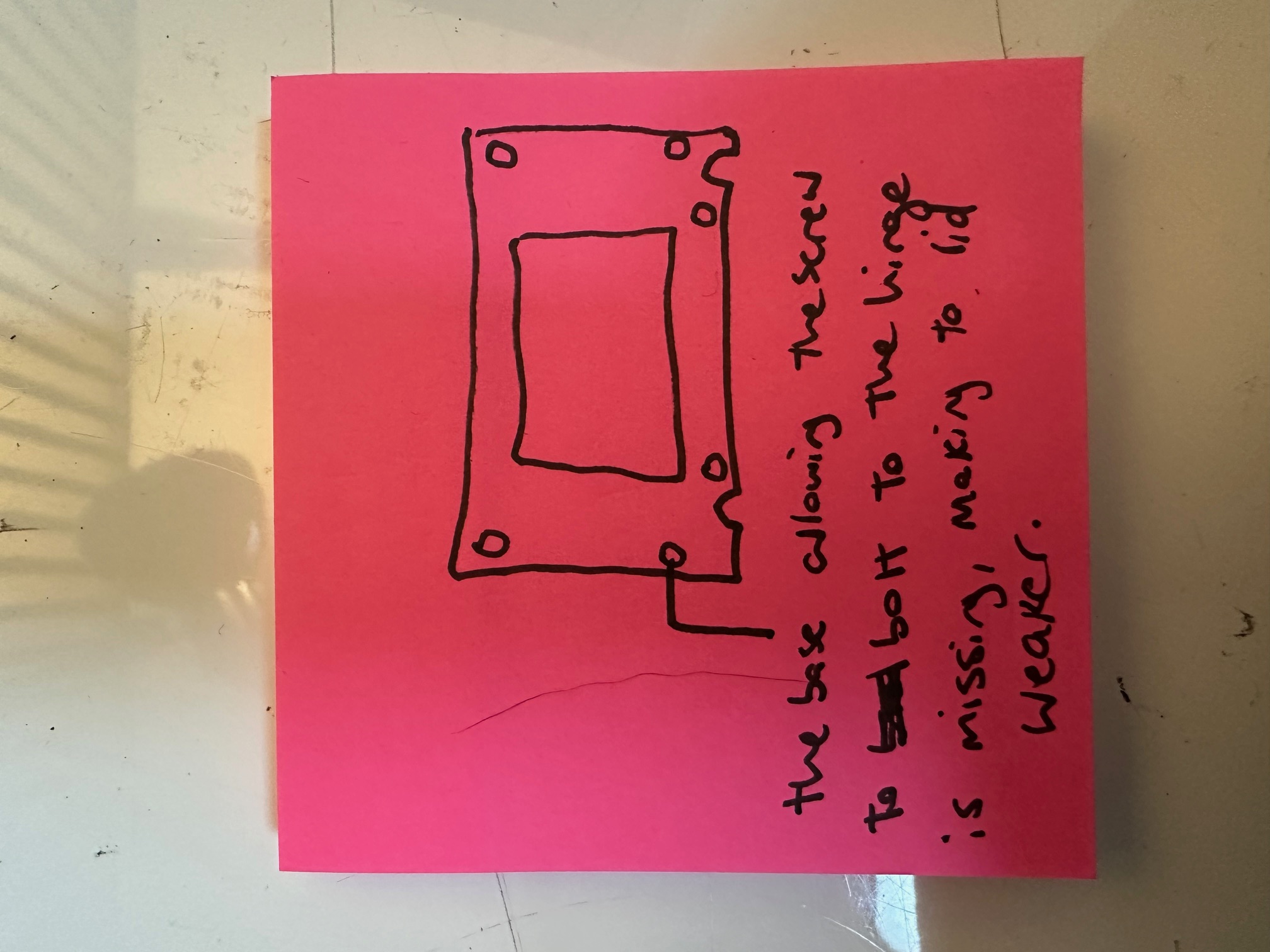
The main issue, which remains is the lid. The hinges are held tight by 3 different screws on each hinge - the middle one on each side screws directly into the lid which is seperate from the front LCD bezel and all the display electronics. Then the outer screw of each hinge passed all the way from the front LCD bezel, through the hinge to the lid and the inside screw the same (but along the bottom of the bezel). This means that when you lift the lid, those 2 inner and 2 outer screws passing front to back, through the hinge are doing a lot of the structural support heavy lifting.
I had two issues - on the left/bottom of my lid, the brass, threaded screw supports had come out of their circular bases in the lid. I superglued these back in position but failed to notice that on the LCD bezel, each of those 4 screw holes obviously has an inner, sunken ring for the screw to bolt-down onto, to secure it's tightness to the lid. The far left one has long since snapped off and gone, so after putting it all back together, whilst I have improved the integrity of my lid, by re-gluing the supports, I'm still down to 75% tightness because my front/left screw isn't bolted tight against anything in the bezel. This means that my left side of the lid is floppy and loose.
I have several 755CX lids and whilst I know the ribbon cables are different, I have not tried swapping the front LCD bezel around, which I may try next.
You could say this was disappointing but at least I know what to do next!
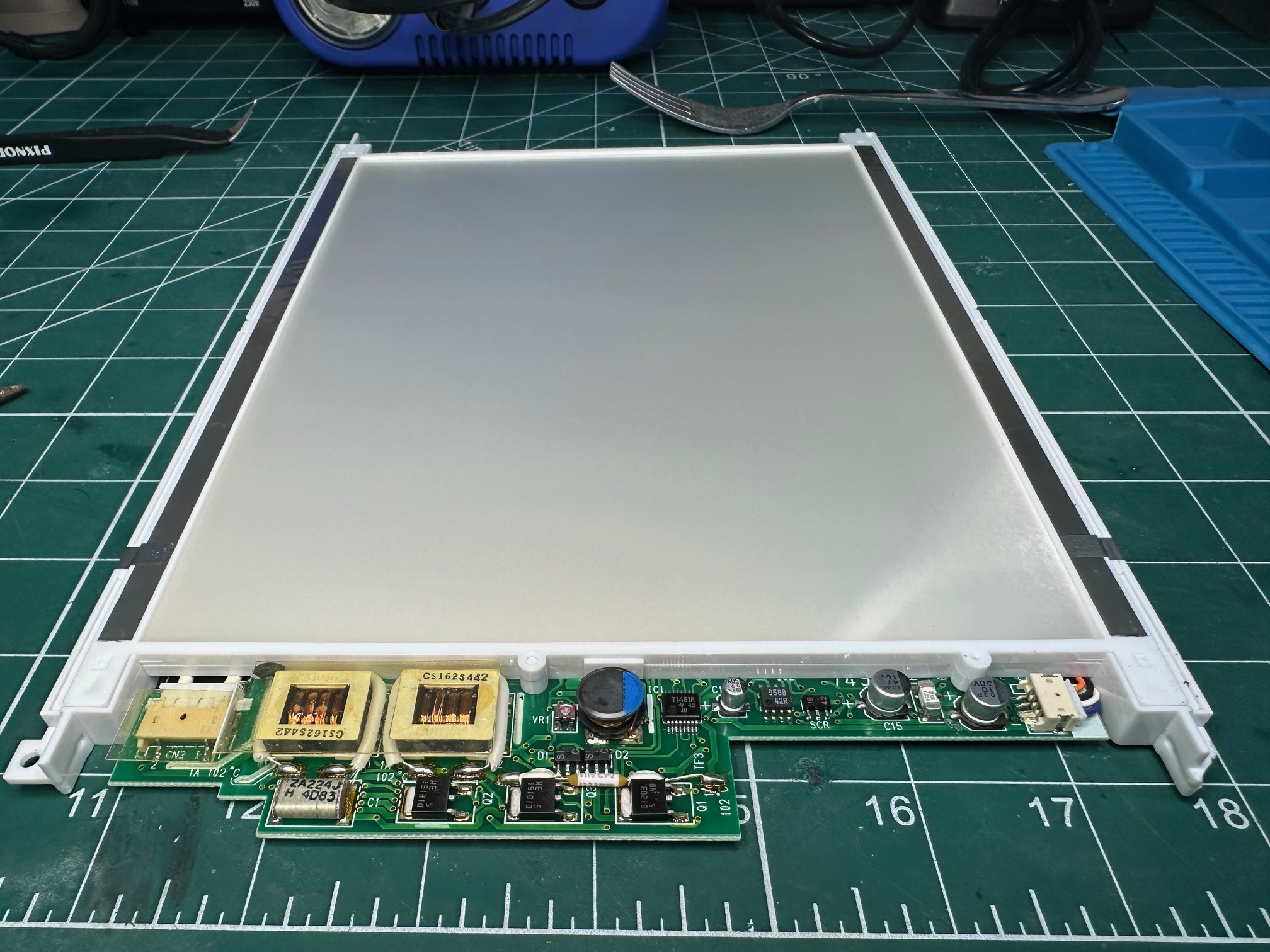
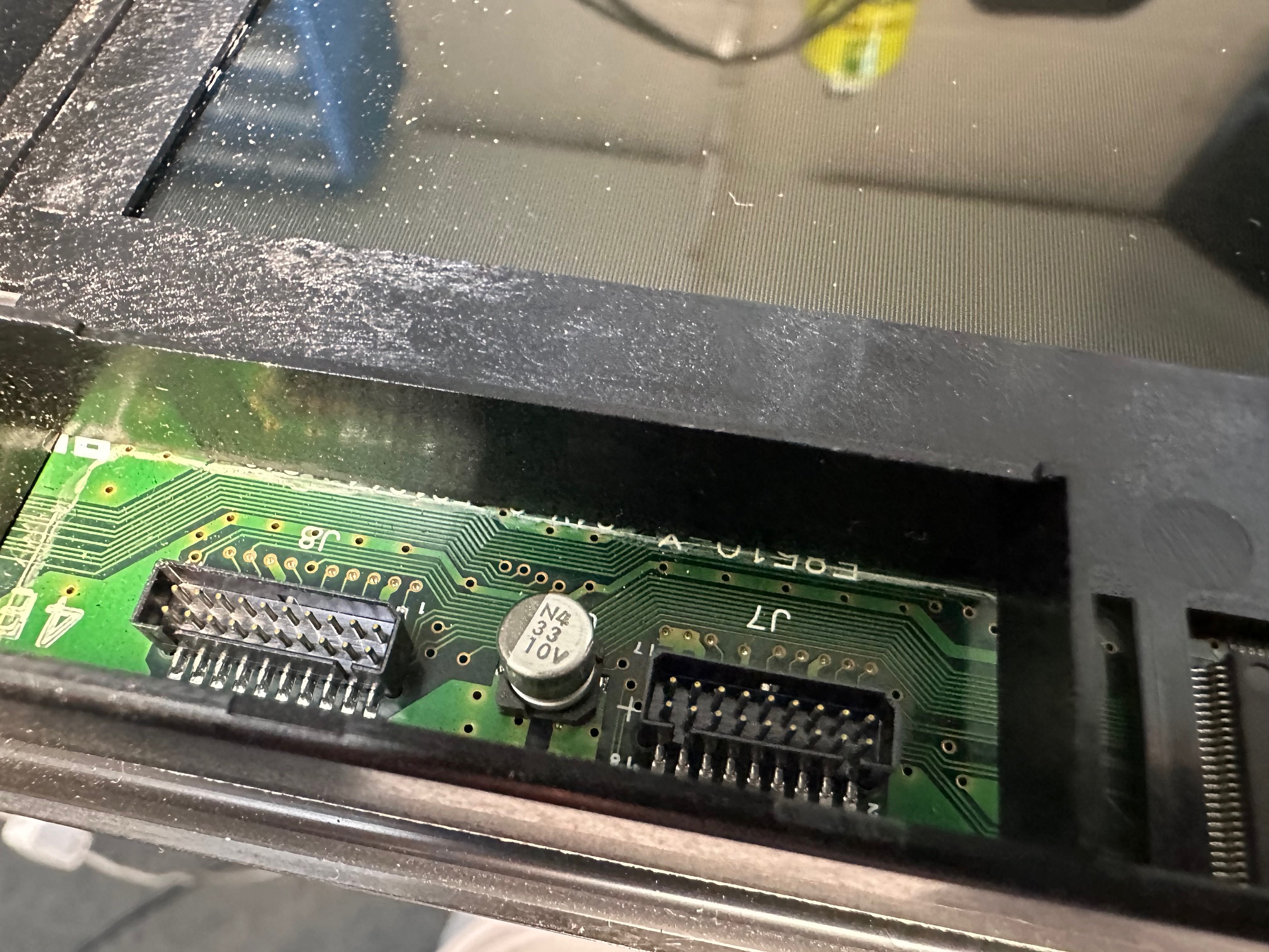
Whilst the lid was off, I investigated the capacitor situation within the LCD assembley. The 755c has 3 different PCBs within which each have their own capacitors.
This is the rear of the assembly, removed from the LCD bezel:
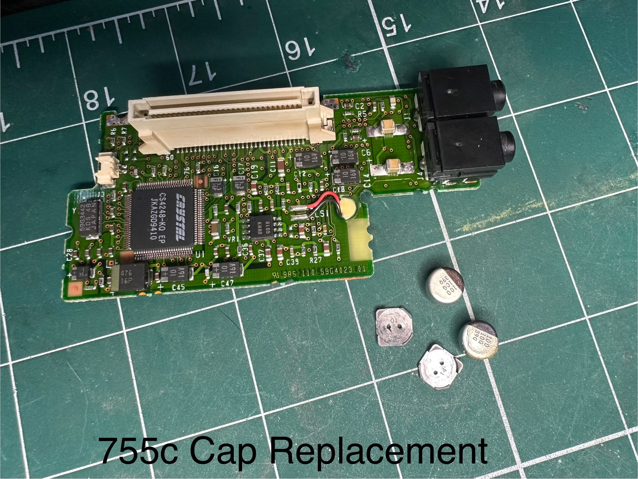
First we have the PCB which is attached to the large white backing and CCFL lighting which has 3 surface mounted caps. 2 of the 3 had leaked and had crustyness all around their bases. This is before:#
And this is after:

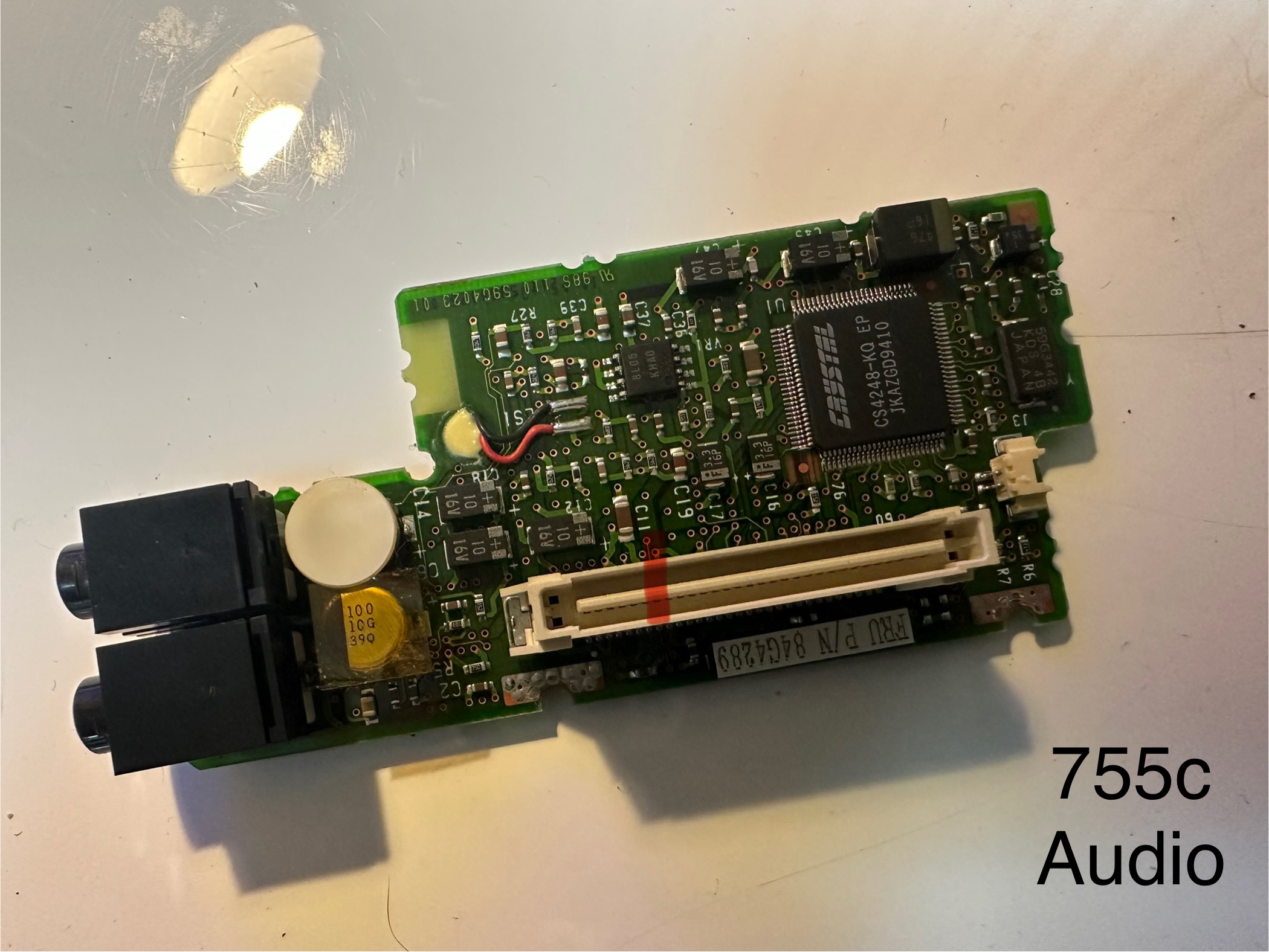
The small board which connects to the thin display ribbon has a single surface mounted electrolytic:
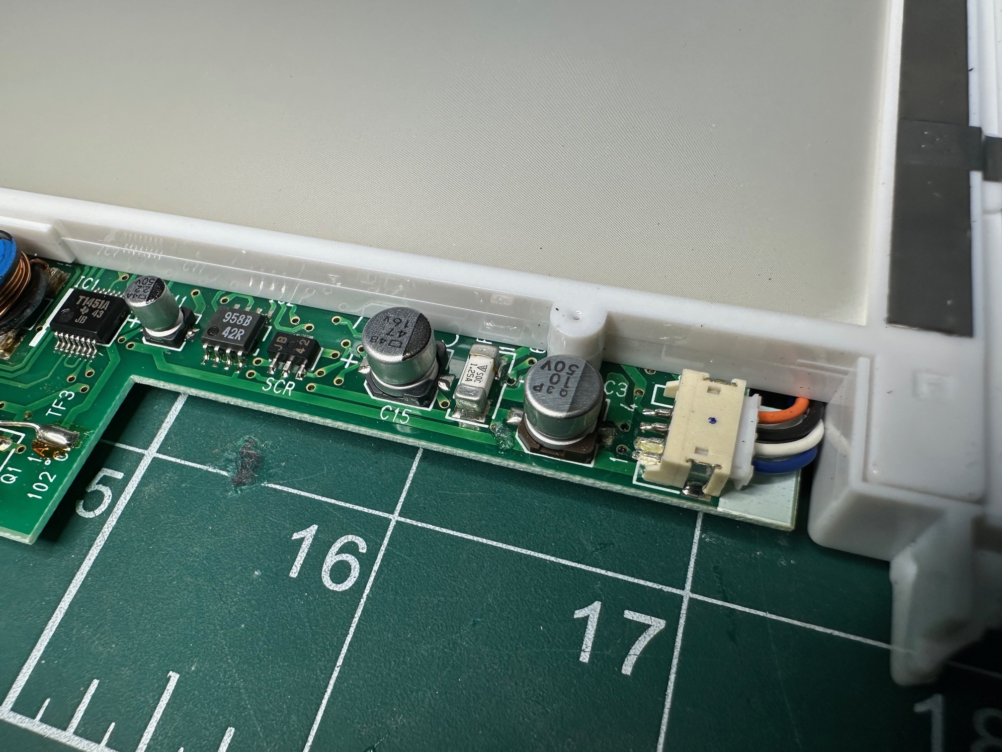
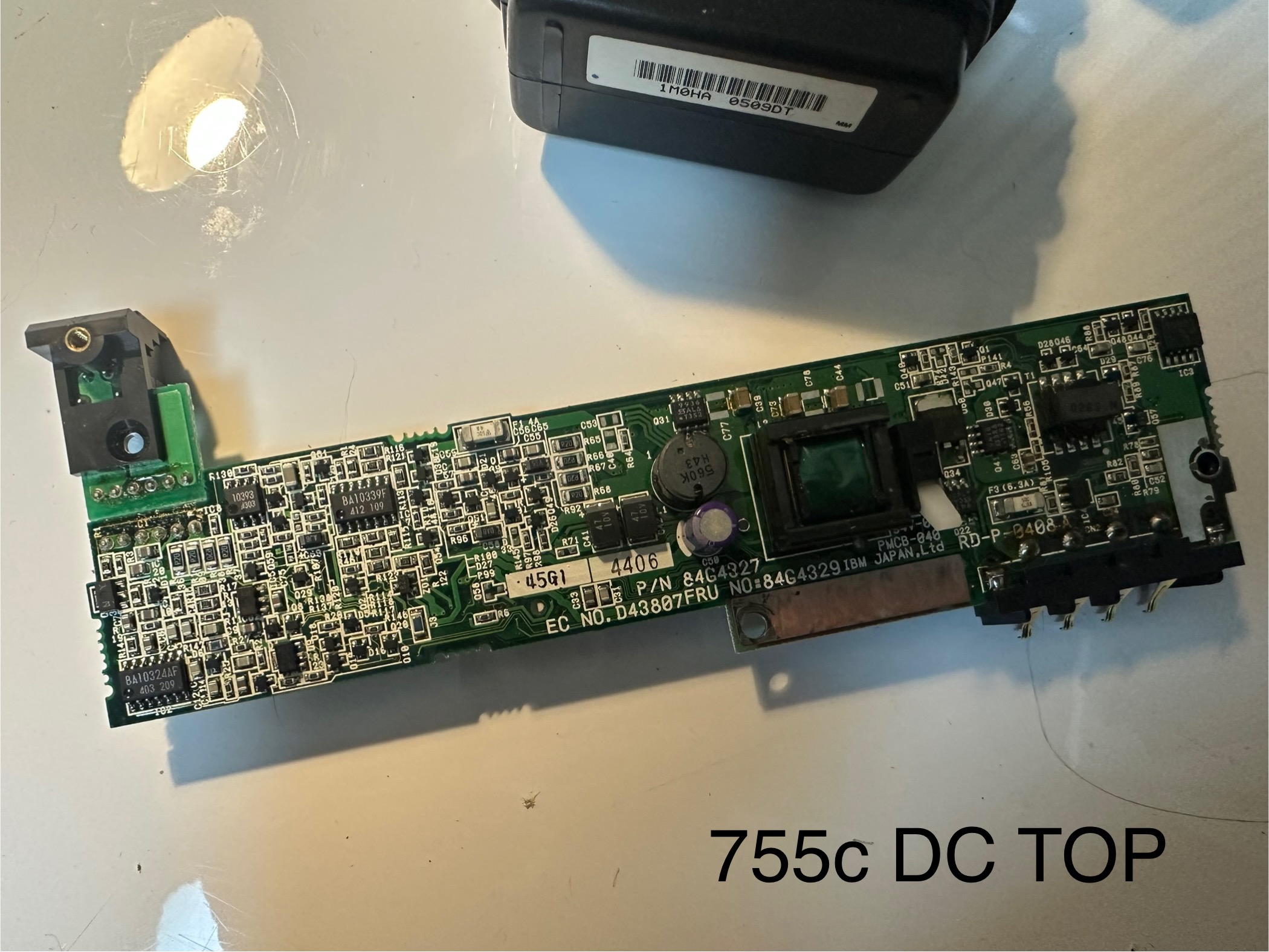
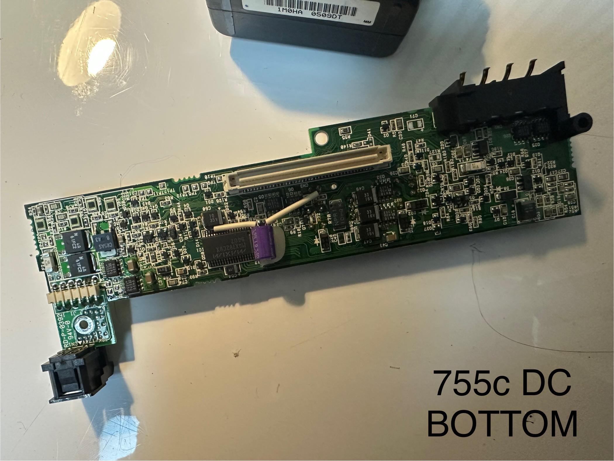
And finally, the inverter, with the brightness and contrast controls, which is connected in the middle to another PCB has the most leaking caps:
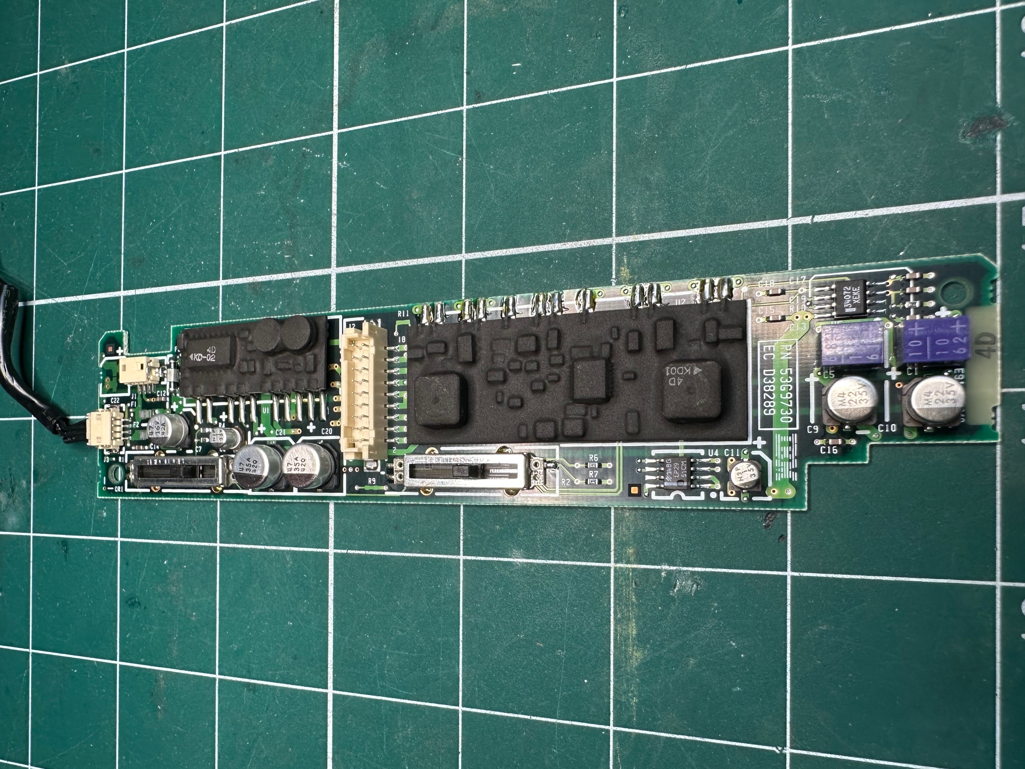
I replaced all my caps with solid ceramics or tantalums with no problem. Where possible I tried to keep the values as close as possible. Worth noting those two purple blocks are also electrolytic capacitors which are side-mounted.
Finally, this one had a german keyboard and both the plastic tabs which hold it down to the base had snapped and long lost (as they often do). The keyboard generally still holds fast, but I did have a spare UK one which still had a damaged left side but good right side (and correct keyboard layout for me), so i swapped it in.
Some notes regarding the insides. Here are some pictures of the different boards:
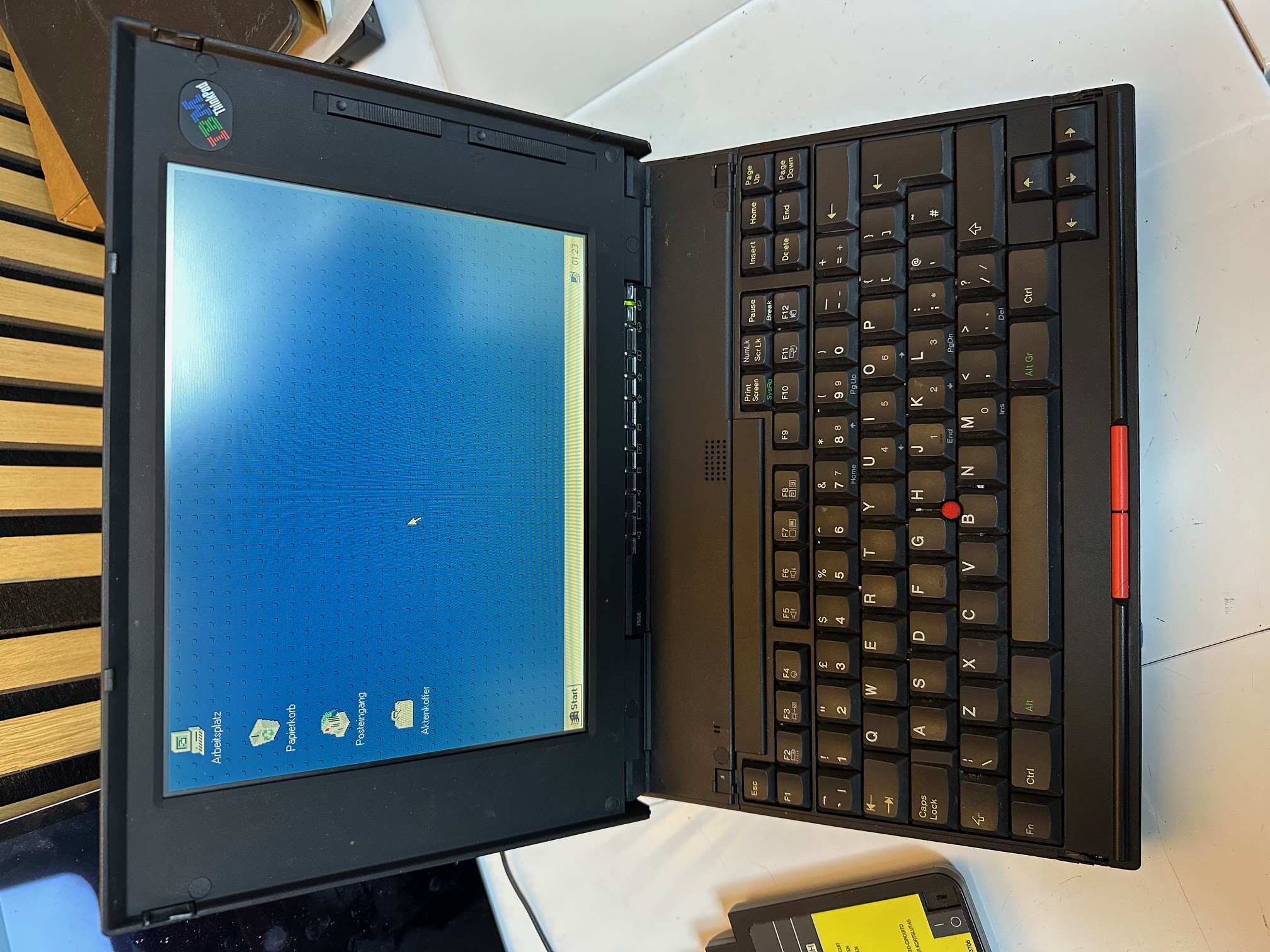
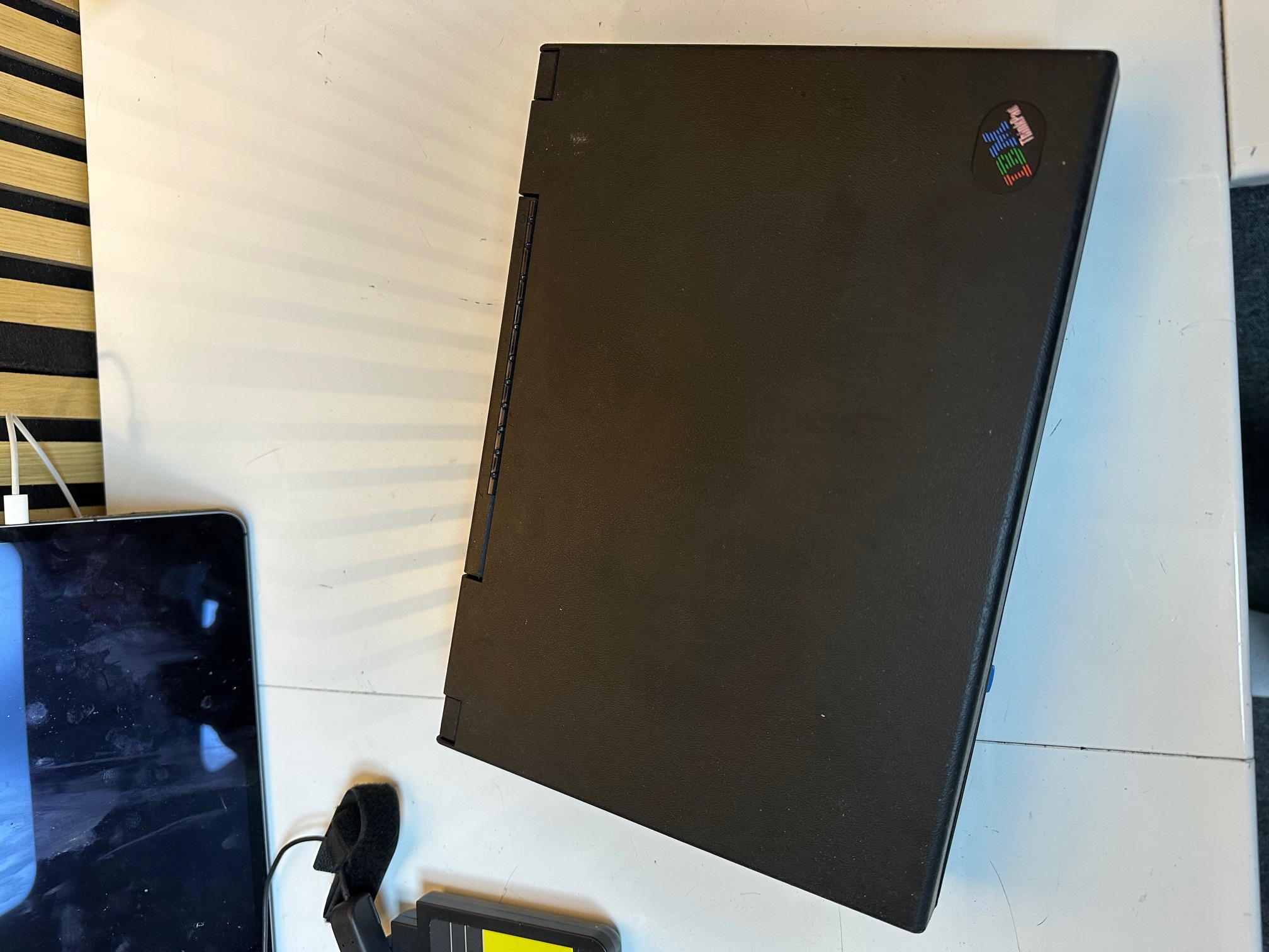
Just for the sake of documenting it all, here is another 755c in my collection. A nice example...


