I ended up with a non-working 755CE and a load of parts from previously dismantling a 755CX and decided to see if I could use the doubles of a lot of the parts to test everything and see if I could repair either machine.
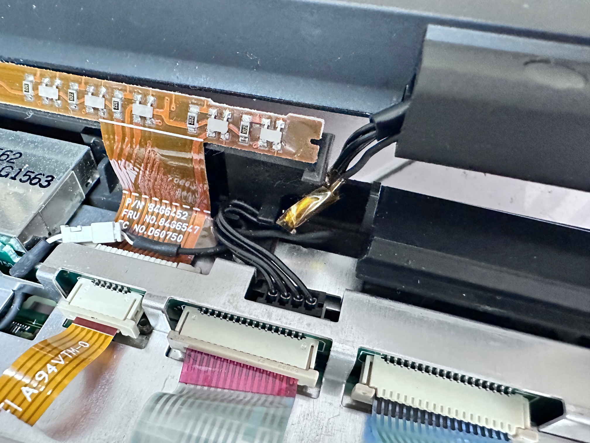
When dismantling either machine, this run of the LCD's power cable (to the inverter) and the lid's microphone cable are shown here, to be tucked out of the way to get the LED bezel back on:
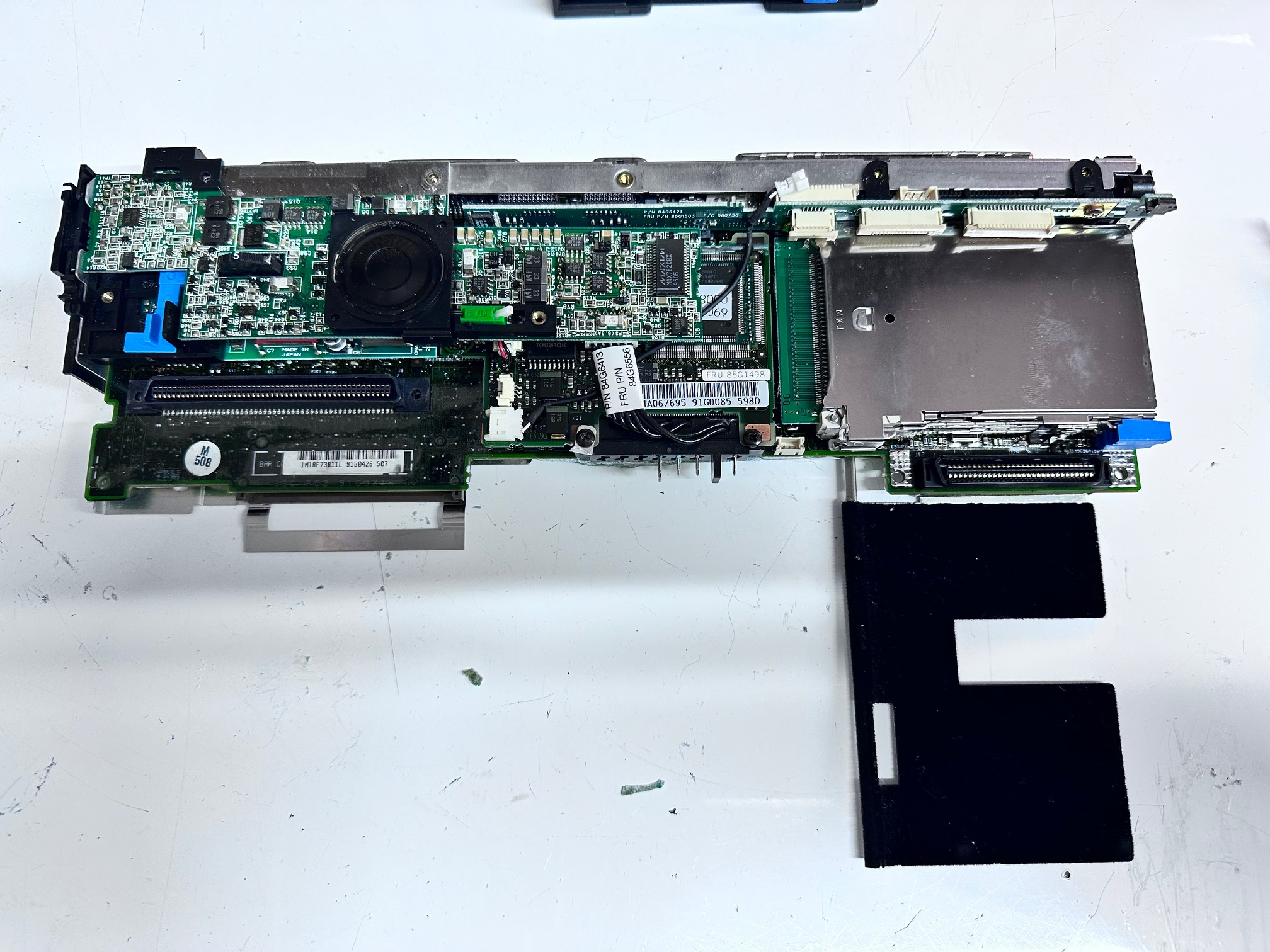
Here is the 755CE board removed from the base. What you're looking at is the motherboard buried underneath almost everything you can see. At the top, with the speaker and the green switch (which detects when the keyboard has been lifted), is the audio board with volume control which is not screwed down. It latches on the left onto the push on/off switch. The top audio board is also wired to the main battery connector which sits underneath the board underneath this board. If that's pulled up and out, you will see the DC power board, which is actually two boards joined in the centre with a push connector. It's got one screw holding it down, just above that blue bit on the left (which is a push-out connector for the optional modem).
The whole massive velvety black section bottom-right is the heatsink for the CPU daughterboard, which also just push-pull unclips from the bottom.
So remove the motherboard from it's metal frame, you need to remove all the connector bolts on the back and two M2.5 fat screws above and below the PCMCIA bay.
Also on top, just below the rear connectors is the interposer which is a small interposing board, which connects the motherboard to the LCD, the LED indicator board and all 3 keyboard connectors.
On the CE only you'll also see this small black plastic spacer back-left which sits underneath the metal plate covering the top and goes ontop of all the boards:
Some Daugherboard Notes:
Here is the top audio board...which is exactly the same (MWAVE) on the CE and CX.
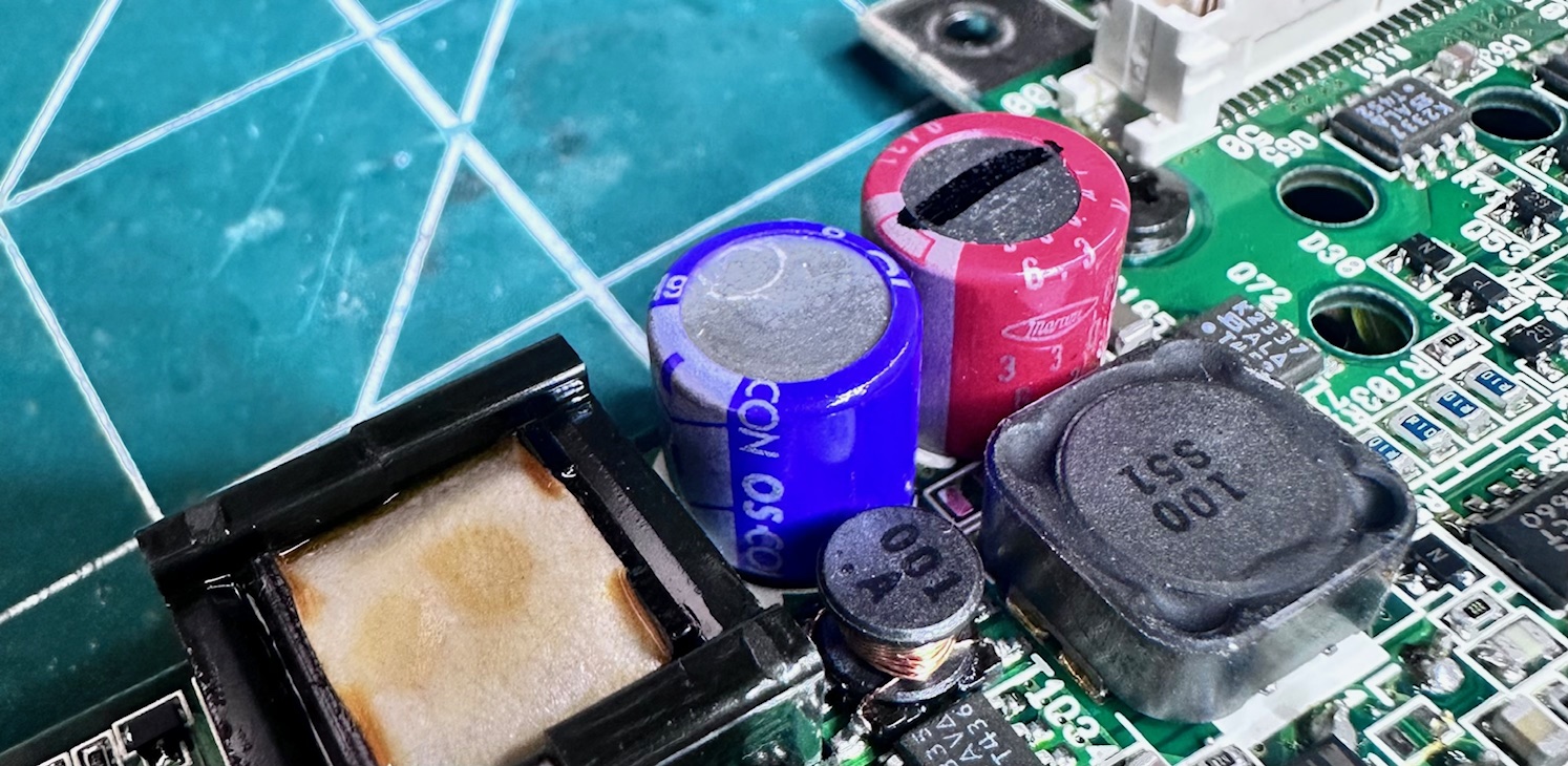
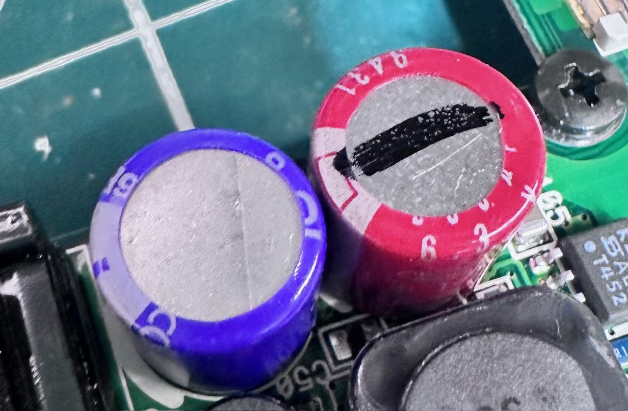
These are the two original capacitors on this DC power board. They don't seem to leak but I always replace them just because a lot of this era do.
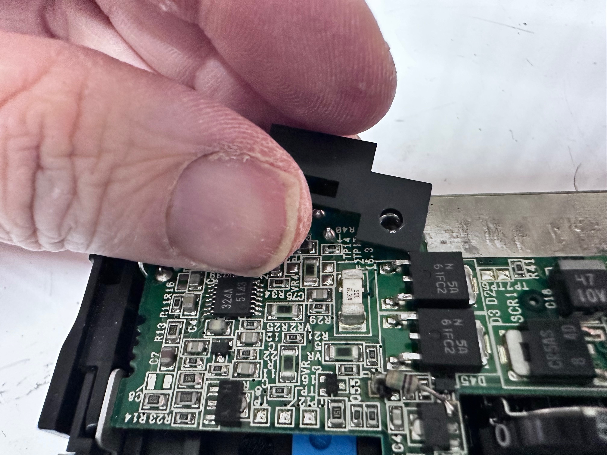
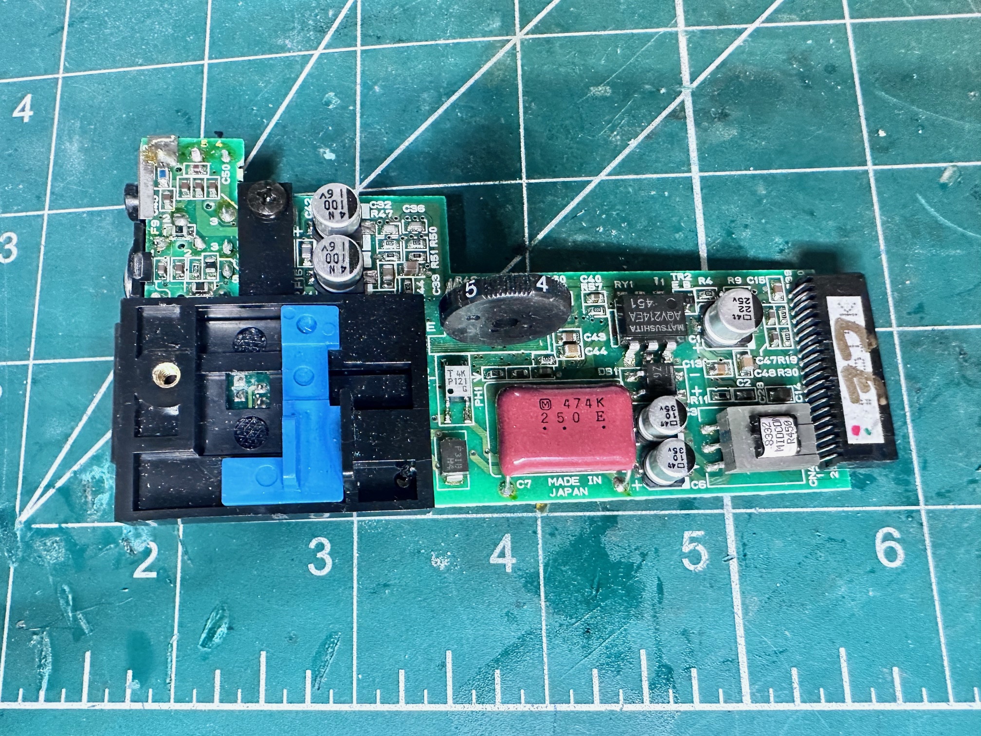
And this is the left side of the DC board with 5 surface-mounted electrolytic daughterboard - the bit with the power connector and volume control on it. I believe these are the same on both the CE and CX but I can't be sure as I no longer have the one for the CX:
Here we have two images showing the bottom heatsink detachable CPU boards. As you can see these are extremely different but actually interchangable between the CE and CX and usable, but I don't know if maybe the CE motherboard is then missing components needed for full CX compatibility. The CE board is a 486 DX board, extremely simple with a few bolts connecting the above and below layers of the heatsink (removed in this picture):
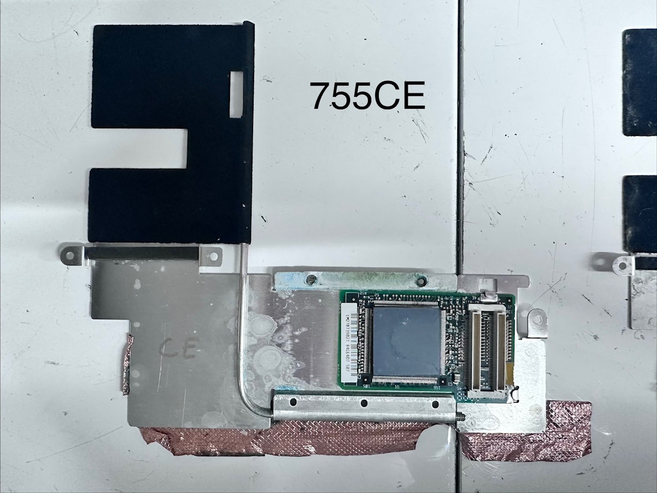
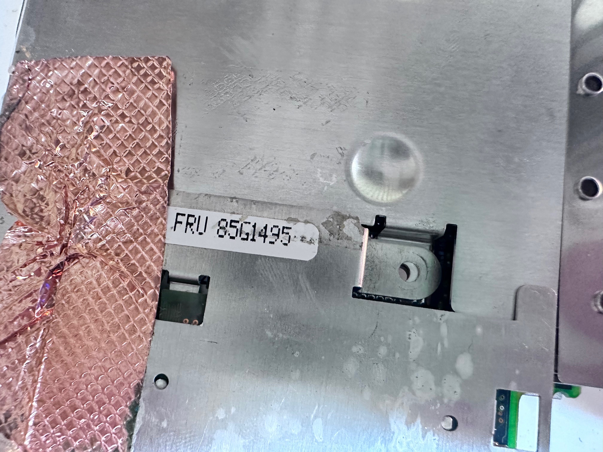
The 486 CPU and heatsink have this part code on them:
And here we have the 755CX board which has the Pentium 75 CPU and a bunch of accompanying chips which might mean that everything CX/Pentium required is on this daughterboard and not the CE/CX motherboard. But this I don't know for sure:
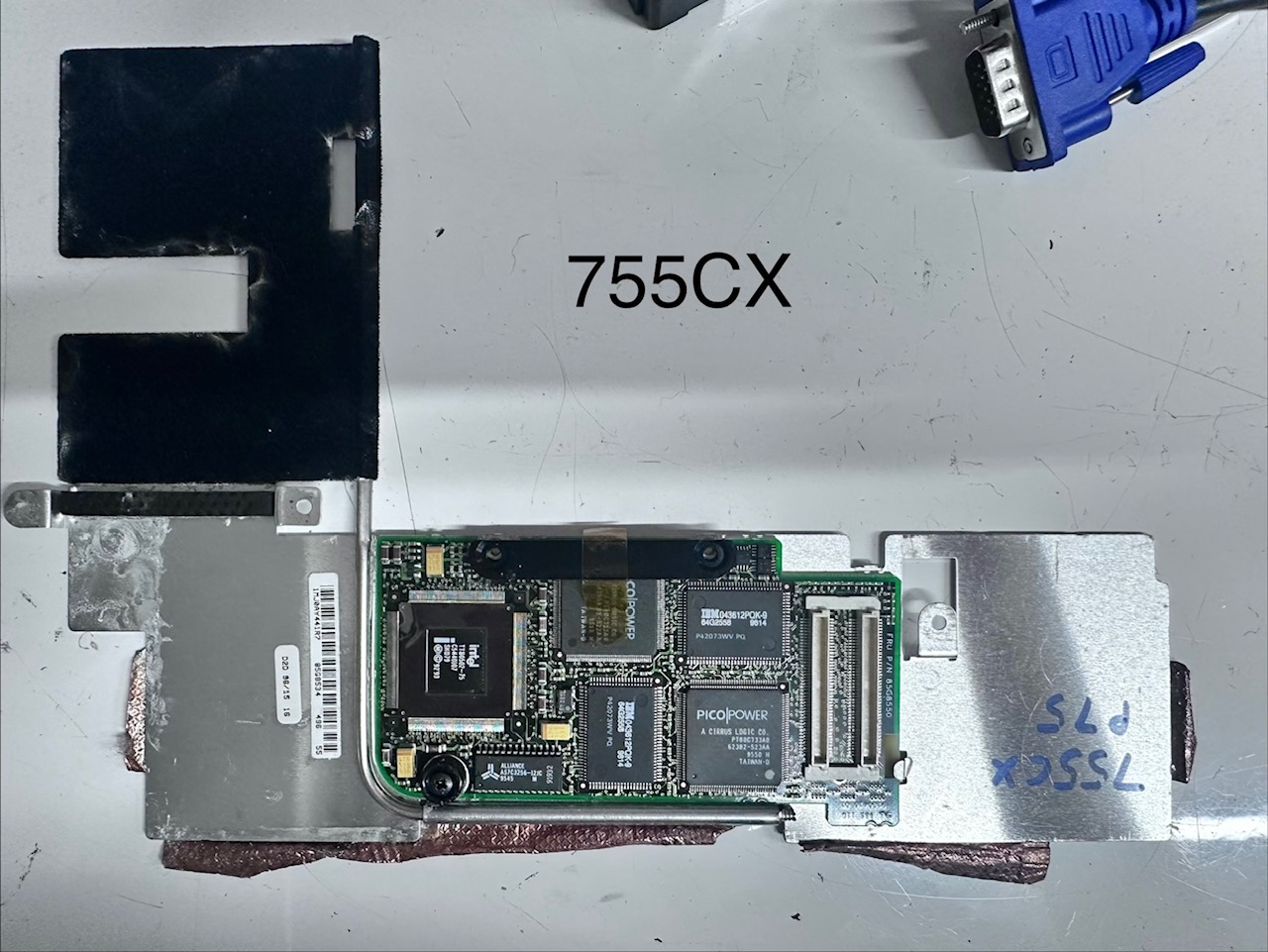
Note that both boards have that copper covered tape around them which help transfer heat onto the shell of the motherboard.
Memory
Addendum. Future me writing here. You can only swap 486 RAM with 486 RAM and Pentium RAM with Pentium RAM. In the writeup here, I have assumed 486 and Pentium RAM are interchangable which is why I did it and got errors in the Easy Setup test facility. 486 RAM has parity and Pentium RAM is not, besides the fact they run at different FSB speeds. /end of future me!
The next problem I faced is that I know the later 755 machines suffer from memory issues with the 'on board' off-board memory (I think this is just accidentally mixing up 486 and Pentium RAM). These later 755 machines do not have RAM soldered on-board and instead have them on a small double-connector daughterboard, in the least-accessible location, underneath the CPU board and inside the deepest part of the motherboard and it's metal chassis. So not only do you have to dismantle the entire machine to get to it, you almost have to rebuilt the entire base to test it - and keep going backwards and forwards as you test and check.
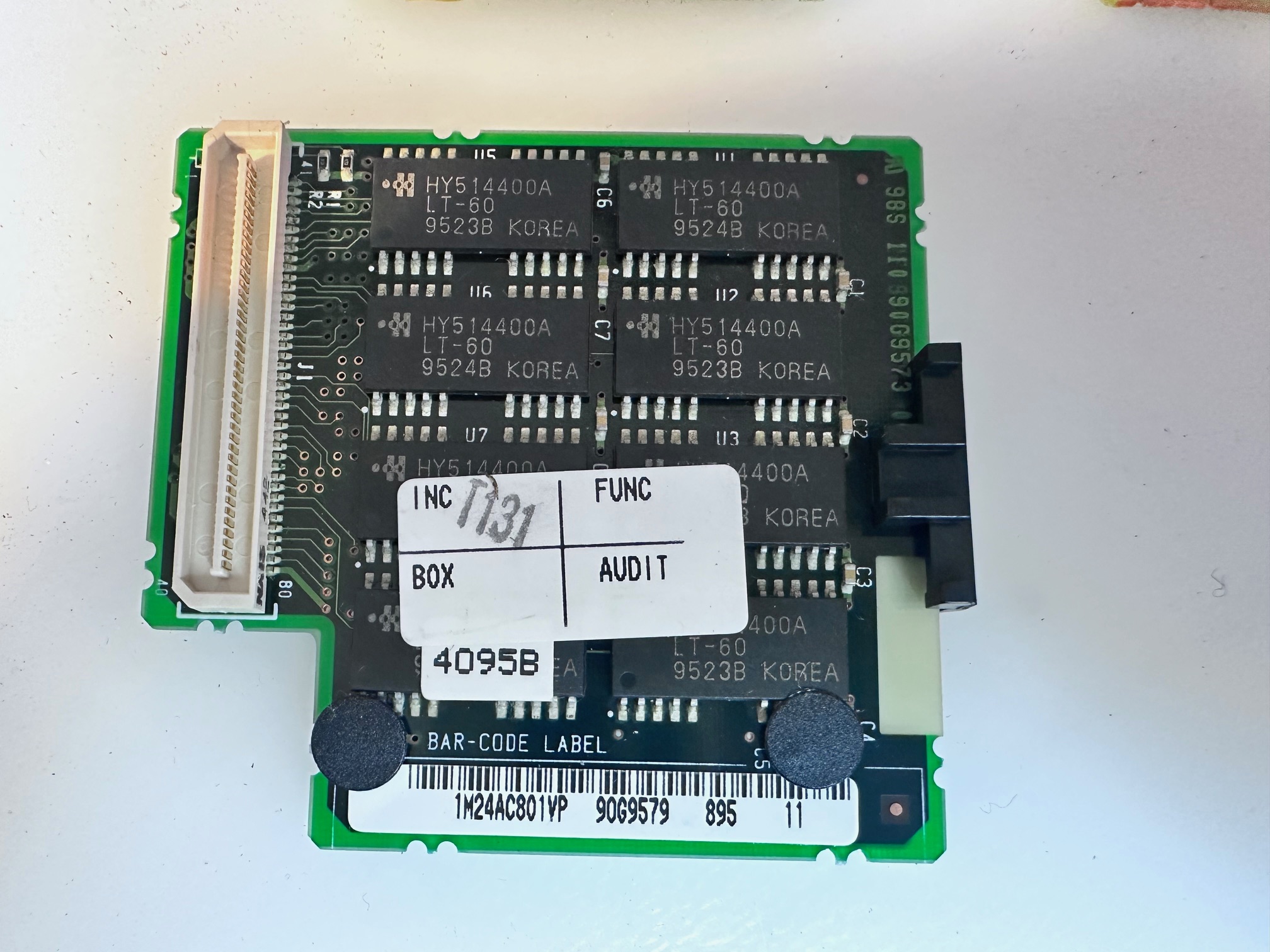
Here is the memory daughterboard with the 755's motherboard upside down and it's metal cage removed:
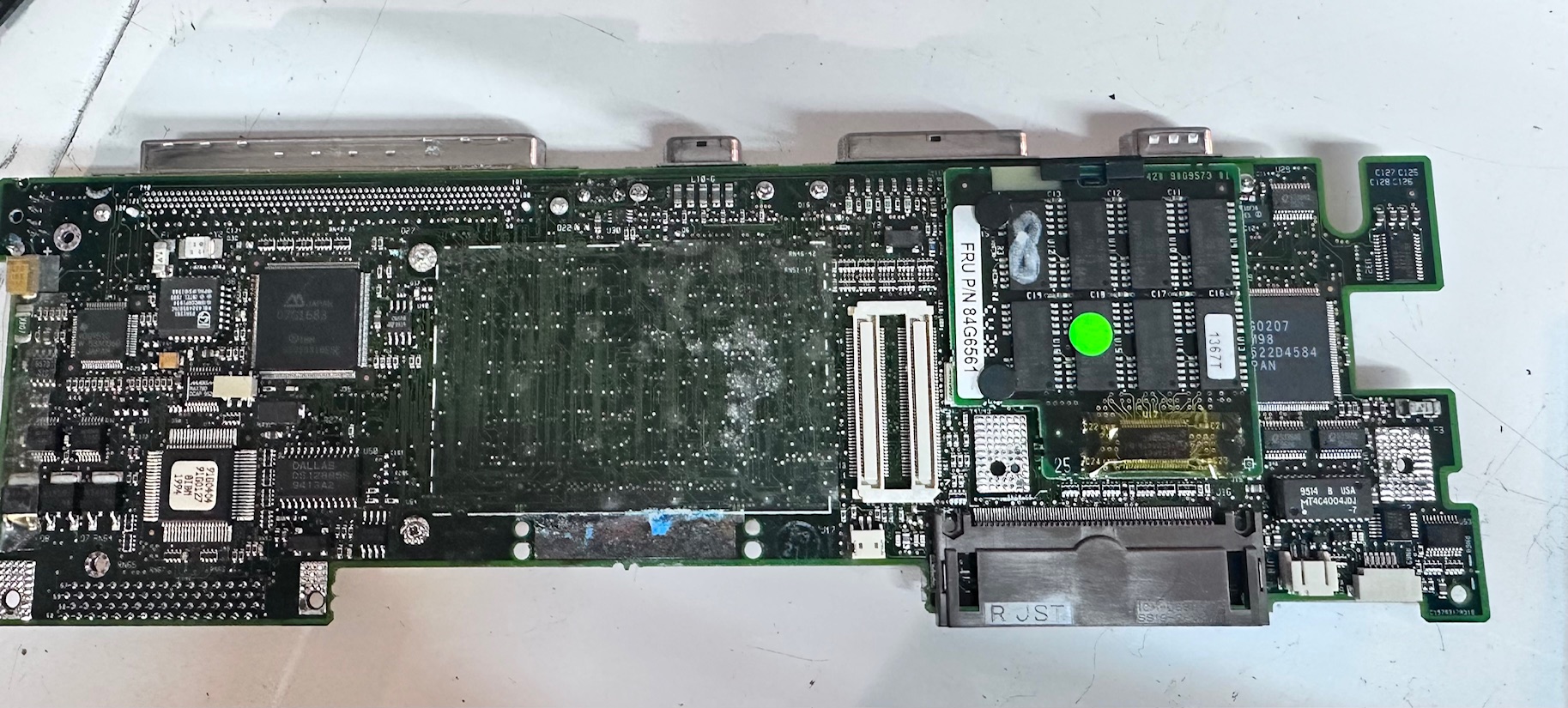
Secondly the CX uses a memory board which has the same dimensions and connectors as the other later 755 motherboards, and the machine will boot, but display similar memory errors that would occur if the machine had a faulty board. This is the board for non-755CX:
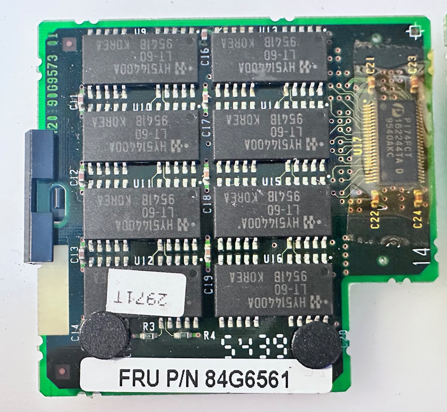
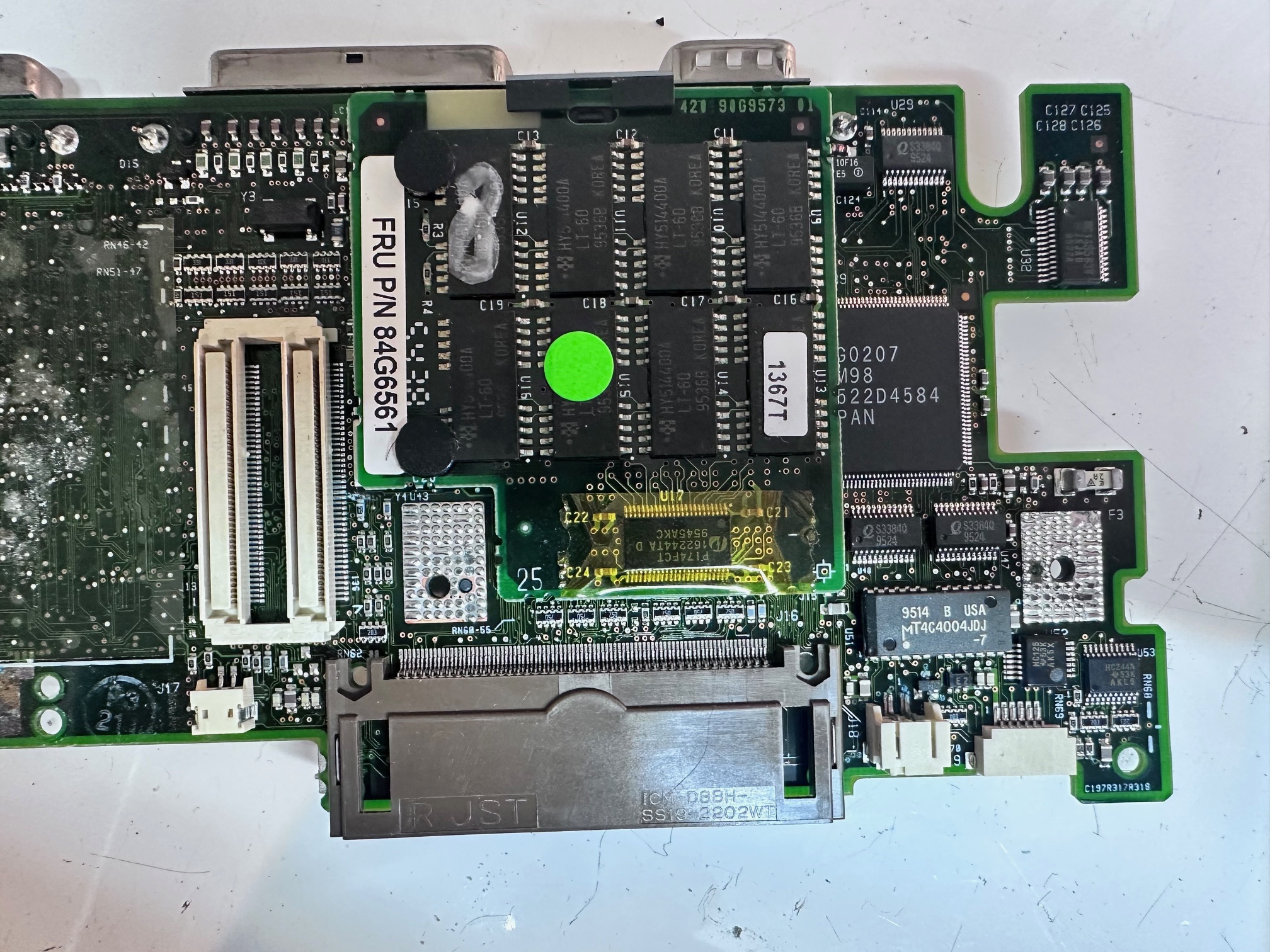
And these are the boards, I think are only for 755CX machines:
These boards connectors are keyed exactly the same, and the machine will boot to Easy Setup, but won't go any further if you get them the wrong way around. On the CX you'll get something like this (ignore the system board error, it's just that I don't have the front/rear IR connected):
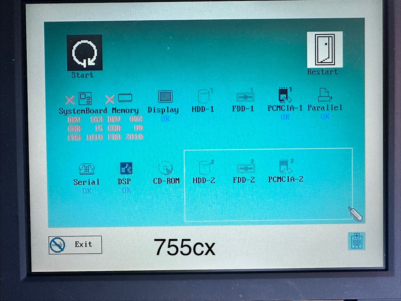
If you manage to get a good RAM board, which matches the type required for your 755 variant and you get it all back together with both IR boards connected, you'll be rewarded with this:
Lids and LCDs
You physically can mount a 755CX lid, panel and it's connectors on a 755CE or 755CV. This is because they're all floppy machines with the same chassis size. The issue in this particular configuration is that the 755CE video board is not capable of outputting SVGA. Many 755CX lids are SVGA (not all!), so whilst it will work, it'll be windowed at native 800x600 pixels on the panel but unable to use any more than 640x480.
I personally would not put a SVGA panel on a 755CE because it will just look unfinished - like it's missing it's driver.
The 755CD and 755CDV have much fatter cases. The panel can be swapped in from a 755CX, but the lid is a different shape due to the taller base. Also the 755CD CAN output 800x600 SVGA because it's memory card is better than that of the 755CE.